class: center, middle # EE-281 ELECTRIC CIRCUITS ## Ozan Keysan [ozan.keysan.me](http://ozan.keysan.me) Office: C-113 <span class="meta">•</span> Tel: 210 7586 --- # Review ## Ohm's Law (Resistivity, Conductivity) -- ## Kirchhoff's Current Law -- ## Kirchhoff's Voltage Law -- ## Node, Branch, Loop, Mesh --- # Analysis Methods ## Scalability? <img src="http://www.k8iqy.com/qrprigs/2n26/2n26txrevcd.gif" alt="Drawing" style="width: 600px;"/> --- # Analysis Methods ## 1-Nodal Analysis ### Unknown: Node Voltages ### Uses Kirchhoff's Current Law -- ## 2-Mesh Analysis ### Unknown: Mesh Currents ### Uses Kirchhoff's Voltage Law --- # Steps for Nodal Analysis ## 1-Choose a reference node (ground). ## 2-Label node voltages. ## 3-Write KCL equations for each node. ## 4-Solve the equations. --- # Choosing Reference Node - ### Node that interconnects the most branches. -- - ### Usually at the bottom of circuit. -- - ### Label ground with one of the symbols below: 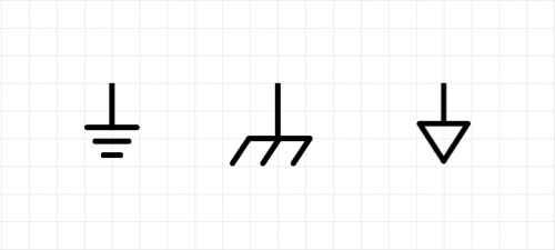 --- # Label each node voltage: ## Except the ground node!  --- # Write KCL for each node ## Incoming Currents + Outgoing Currents = 0 -- ## The most practical way: ### Use \\(-\\) sign for incoming currents. ### Use \\(+\\) sign for outgoing currents. --- # Example-1: ## Calculate node voltages: 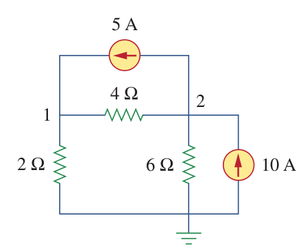 --- # Example-1: Label nodes 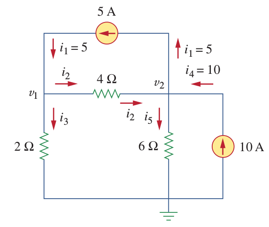 --- # Example-1: ### Answer: \\(V_1 = 40/3 V \quad V_2 = 20 V \\)  --- # Example-2: 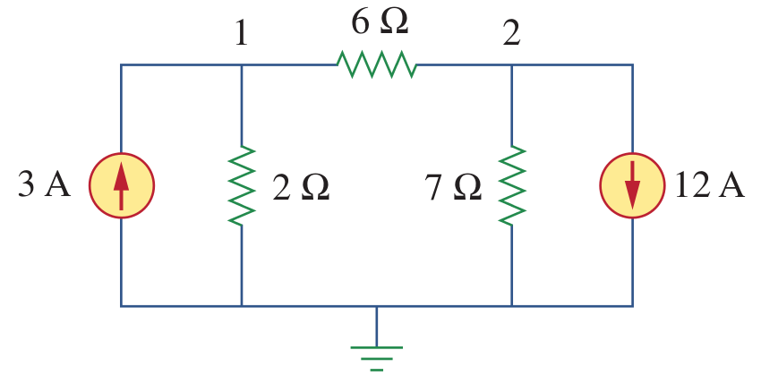 --- # Example-2: ### Answer: \\(V_1 = -6 V \quad V_2 = -42 V \\)  --- # Dependent Sources ## Dependent Voltage Source  ## Shown with a square sign ## Its value is dependent on another variable --- # Dependent Sources ## Dependent Current Source  ## Shown with a square sign ## Its value is dependent on another variable --- # Dependent Sources ## Dependent Current Source  --- # Example-3: 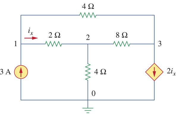 --- # Example-3: ### Answer: \\(V_1 = 4.8 V \quad V_2 = 2.4 V \quad V_2 = -2.4 V \\)  --- #Example: ## Obtain resistance matrix for:  --- #Example: ## Obtain resistance matrix for: 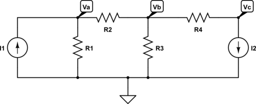 --- # Example: ## Resistance Matrix: $$ \begin{bmatrix} \frac{1}{R_1}+\frac{1}{R_2} & -\frac{1}{R_2} & 0 \\\ -\frac{1}{R_2} & \frac{1}{R_2}+ \frac{1}{R_3}+\frac{1}{R_4} & -\frac{1}{R_4} \\\ 0 & -\frac{1}{R_4} & \frac{1}{R_4}\\\ \end{bmatrix} \begin{bmatrix} V_a \\\ V_b \\\ V_c \\\ \end{bmatrix} = \begin{bmatrix} I_1 \\\ 0 \\\ -I_2 \\\ \end{bmatrix} $$ --- # Example: ## Remember! ## Conductance = 1/ Resistance ## $$G = \frac{1}{R}$$ --- #Conductance Matrix: ## (Sometimes it is more convenient) $$\begin{bmatrix} G_1+G_2 & -G_2 & 0 \\\ -G_2 & G_2+ G_3+G_4 & -G_4 \\\ 0 & -G_4 & G_4 \end{bmatrix} \begin{bmatrix} V_a \\\ V_b \\\ V_c \end{bmatrix} = \begin{bmatrix} I_1 \\\ 0 \\\ -I_2 \end{bmatrix} $$ --- # No Escape from Linear Algebra! # $$Ax=b $$ -- # $$x=A^{-1}b $$ --- # Any questions? ## You can download this presentation from: [keysan.me/ee281](http://keysan.me/ee281)